

Flocky Ball
Flocky Ball is a modular dome system built from everyday materials. By rethinking the “node logic” behind buckyball structures, we developed a multi-directional joint that grows into a curved, self-supporting shell.
This project won First Prize(Grand Prize)at the Japan Institute of Architects (JIA) International Summer Seminar, competed with nearly 70 teams across Asia .
TYPE: Team project (5) — Academic
INSTRUCTOR: Yi-Hsuan Tu
ROLE: Computational design; prototyping; fabrication planning; photo/video editing
TOOLS: Rhino; Grasshopper; Photoshop; CapCut
Challenges & Constraints
How can we build a human-scale spatial experience using only cheap, everyday items?
For the JIA International Summer Seminar, our team aimed to create a walkable dome that is:
1. light enough and packable for air travel
2. fast to assemble on site
3. structurally reliable and repeatable (not just a one- off sculpture)
4. limited budget
5. off-the-shelf, everyday materials
6. no traditional hardware or glue(no screws, no tape, only mechanical joints)
Research Methodology: The Convenience Store Hunt
Before aiming for precision, we aimed for availability. From medical IV tubes to stationery magnets, we tested every accessible cylindrical object.
The receipts serve as a timeline of our material evolution.
System & Geometry
We started from Fuller’s geodesic geometry. Using an icosahedron as the base, we subdivided and projected the mesh to form a perfect sphere.
Then we looked at the buckyball pattern – a combination of 5-way and 6-way nodes.
''Translating Geodesic Logic to Everyday Objects.'' is the ultimate goal.
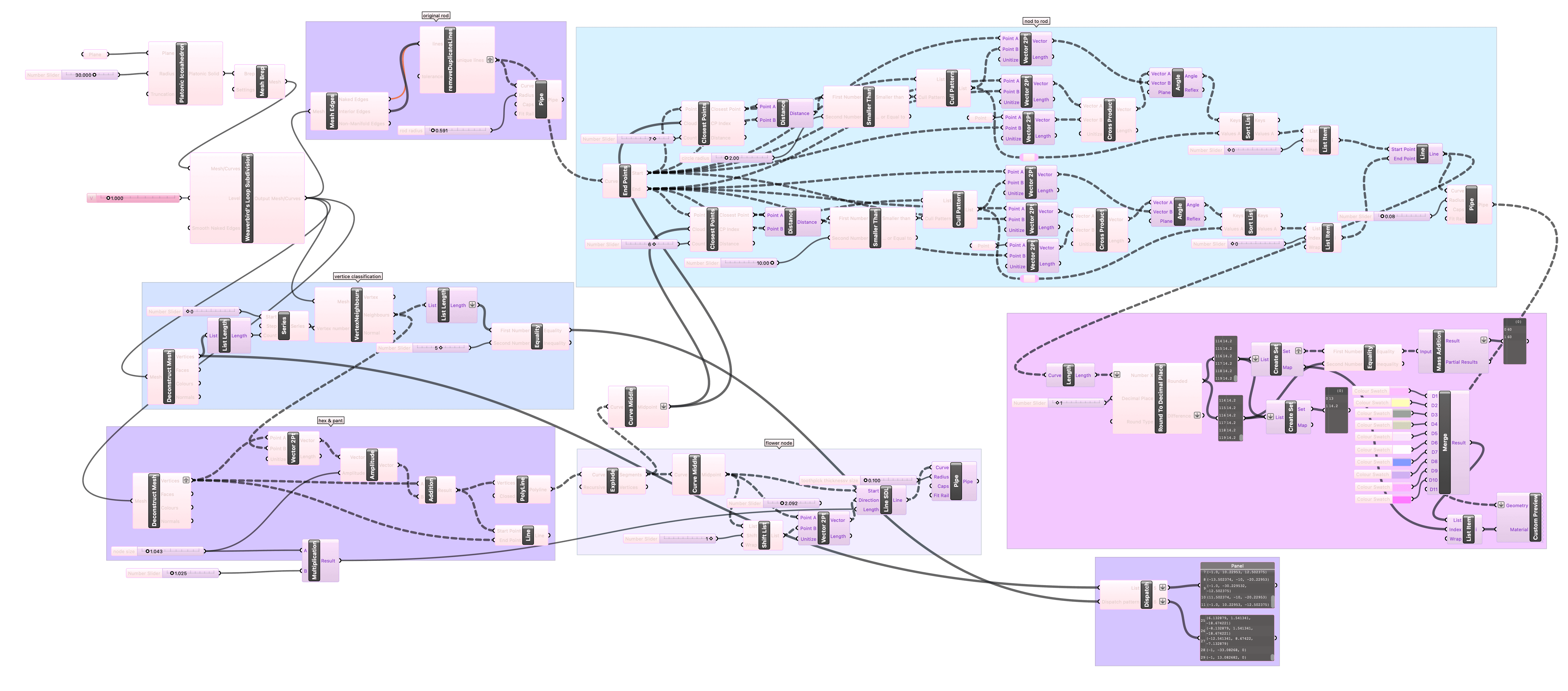
In Grasshopper, I analyzed the mesh topology to strictly separate pentagonal (5-way) and hexagonal (6-way) nodes. This digital mapping was crucial because standard floss picks must be arranged differently depending on their position in the geodesic grid to form a valid curvature.

This diagram shows how the system evolves from a bare geodesic frame to identified nodes to custom joints placed at each node.
1-1
Base Geometry & Spherization
Logic: The structure originates from a Platonic Icosahedron. To transform this low-poly form into a dome, I applied a subdivision algorithm to increase the mesh frequency.
Optimization: Since standard subdivision results in planar faces, a vector-based normalization technique was implemented. This projects all vertices equidistantly from the center, ensuring a perfect spherical curvature (geodesic geometry).

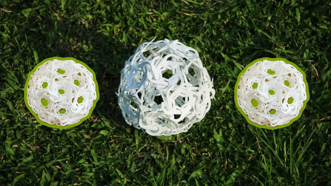
V1 (left), V2(middle), V4(right)

By increasing the subdivision frequency, both the classic Fuller frame and our custom node system move from a coarse icosahedral shape to a nearly continuous geodesic dome.
1-2
Topological Analysis & Classification
Problem: A geodesic dome is composed of two topologically distinct node types: pentagonal (5-way valence) and hexagonal (6-way valence) connections.
Solution: I utilized a Vertex Valence algorithm (via Kangaroo) to analyze the topology and calculate the number of connecting edges for each vertex.
Data Sorting: Using a Dispatch logic, the vertices were automatically separated into two distinct lists. This allowed for the generation of specific connector geometries (5-sided vs. 6-sided) tailored to each node type.

1-3
Parametric "Iris" Joint Generation
Geometry: For each node, a construction plane was generated perpendicular to the sphere's normal vector.
Articulation: Instead of simple radial extrusion, I designed an "Iris-like" mechanism (flower node). By using a Shift List algorithm, vectors were calculated between edge midpoints i i and i + 1 i+1 . This created a rotational, interlocking strut arrangement that enhances the visual complexity of the joints and explains how our node system works.

1-4
Connectivity Algorithm
Challenge: Connecting the custom joints to the main structural frame was geometrically complex due to the skewed axes of the geodesic lines. A simple distance check caused errors where lines would connect to the "wrong neighbor."
Algorithm: I developed a multi-stage filtering system to ensure 100% precision:
1. Radius Filtering: A Cull Pattern based on proximity was applied to isolate candidate points specific to each node, removing interference from adjacent nodes.
2. Cross-Product Logic: To determine the correct connection point on a skewed axis, I calculated the Cross Product of the strut vector and the surface normal to define a precise "side vector."
3. Angle Sorting: The final connection points were selected by sorting candidates based on their angular alignment, ensuring the struts connect perfectly to the articulated joints.

Node & Material Hacking
The node design evolved from abstract geodesic points into a family of physical joints.
Through small-scale prototypes like Ball Uni, Ball Hana, Ball Tamago and different ring and triangle patterns, we tested how each joint type affected curvature, stability and ease of assembly. These iterations helped converge on a joint logic that could scale from hand-sized models to a full dome.
Finally we decided on adopting type6 & type10 as our modular node system.


V1 “Ball Uni” prototype using the Type 55 joint. This version tested a more rigid, frame-like interpretation of the node system.
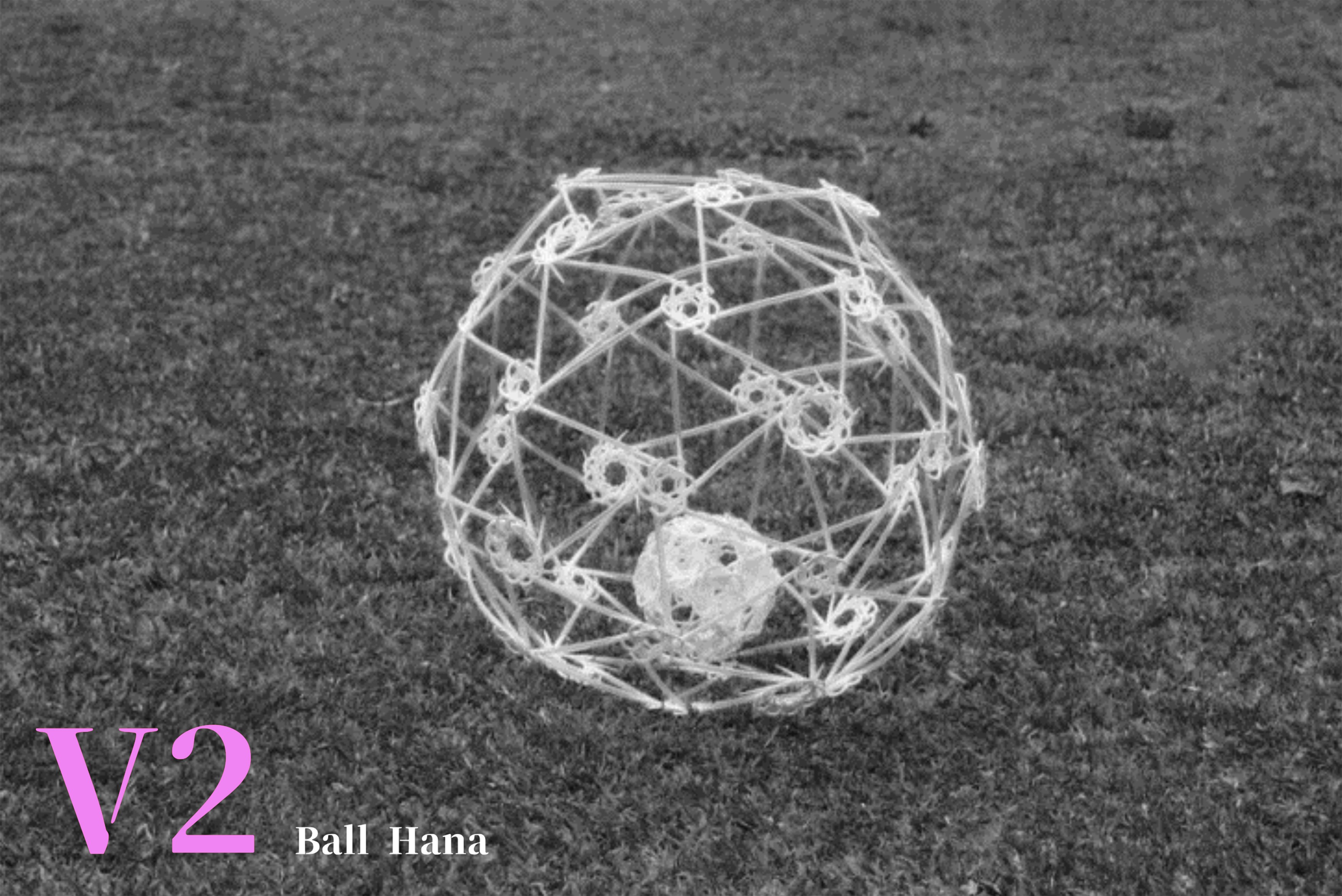
V2 “Ball Hana” explored a flower-like connector that distributes forces through multiple small arms, producing a lighter and more open shell.

“Ball Tamago” focused on how five repeating units lock into a pentagonal cluster, echoing the buckyball’s 5-way nodes.

Comparing Type 10 and Type 6 ring patterns. Different repetition counts lead to smoother or sharper curvature around each node.
This is similar to the lock-in logic of the "Iris" mechanism.

V6 prototypes tested larger triangular fields. By scaling the local triangle, we studied how patch size affects the smoothness and stiffness of the global dome.
Material Logic & Assembly
To translate the system into something anyone could build, we chose specific size & type of floss picks and straws as structural components.
By carefully designing and testing sections, friction points, and lever behavior, the joints could be assembled through simple snap-in actions could gradually grow into a self-supporting shell.
Beyond a regular geodesic dome, the same joint logic can also produce more blob-like, irregular enclosures: only the strut lengths need to be redefined while the nodes and assembly rules stay the same.
The result is a kit that non-experts can learn and assemble through clear, repeatable rules.

-We tried an additional showcase of a blob-like enclosure during the seminar

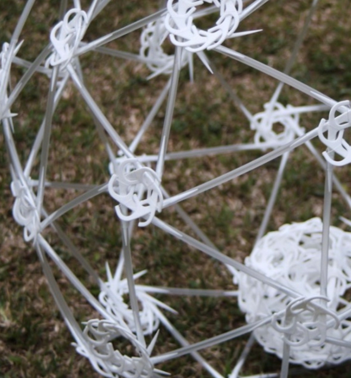
Section studies of the floss-pick joint.
Different angles and contact points generate controlled friction, which later accumulates into global curvature.

Composite joint detail.
A small hose wraps the floss and straw, increasing friction and stabilizing rotation at each connection.

Each joint behaves like a tiny lever.
Forces are passed along the straws, allowing the shell to become self-supporting without a heavy frame.
Parametric Fabrication
Because the entire dome is parametrically defined, every fabrication parameter can be controlled: node counts, strut lengths, node sizes and geodesic level. The model outputs cutting lists and assembly logic directly from the script, turning the dome into a scalable kit-of-parts rather than a one-time installation.
4-1
Geometric Logic & Quantification
By analyzing the subdivision logic of a high-frequency Fuller Dome (e.g., v6), it becomes evident that visual uniformity is deceptive. What appears to be a regular pattern actually consists of multiple distinct edge lengths (mapped here as Types A through Types I). Recognizing that these 'similar' edges are not 'identical,' I established a rigorous quantification protocol in Grasshopper. This pre-fabrication analysis prevents cumulative errors by precisely calculating and grouping each unique strut type before production.

4-2
Structural Analysis & Fabrication Data
Tolerance Management: Computational precision often leads to microscopic floating-point errors (e.g., 500.001 vs 500.000). To solve this, I converted numerical data into Text Strings after rounding, ensuring identical strut lengths were grouped correctly.
Data Classification: Using Create Set and Map logic, the hundreds of struts were classified into distinct types based on length.
Visualization: A custom color-coding system was applied to visually map the different strut lengths, while Mass Addition was used to automatically generate a precise Bill of Materials (BOM) for fabrication counting.


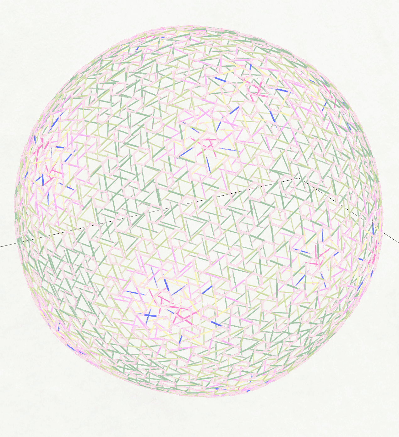
Tolerance Sensitivity Analysis


This comparison demonstrates how floating-point precision affects the categorization of structural struts for fabrication.
Node Classification

Vertex valence analysis counts all 5-way and 6-way nodes and maps their exact positions.
Result & On-Site Construction
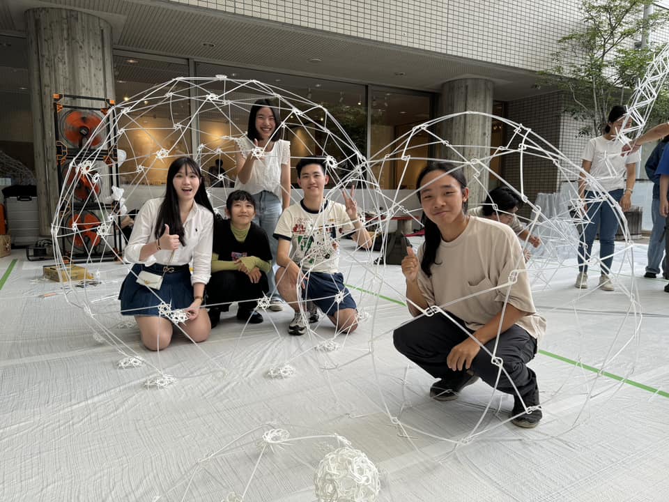
The final construction validated the system's scalability and practicality. By calibrating the geometry to human-scale use(1.7M), material availability(straw length<60cm), and transportation limits(single suitcase for air-travel), the dome could be fabricated and assembled entirely on site within half an hour.
V3 Dome was chosen for exhibition deployment due to its compatibility with off-the-shelf components, enabling rapid assembly and reliable structural performance.
Beyond the final structure, multiple on-site prototypes were constructed as reference studies, demonstrating the system's flexibility and potential for reuse across different contexts.


Full-scale pre-deployment assembly in Taiwan. The system was tested at human scale prior to shipment, verifying material tolerances, assembly logic, and structural stability under real fabrication constraints.


Unit-based extension beyond architectural scale. Using the same structural logic, additional prototypes—a furniture-scale vase inspired by nanotube geometry—were fabricated to demonstrate the system's cross-scale adaptability.

By mixing V2 and V3 modules on site, the team explored irregular, blob-like forms, revealing the system’s tolerance for emergent geometries beyond predefined assemblies.